A resistor is a two-terminal passive electronic component that blocks the flow of electric current. It does not create energy but controls how energy flows in a circuit. Its main functions include:
Limiting current to protect sensitive components from damage.
Adjusting voltage distribution to set reference levels in the circuit.
Turning electric energy into heat, which is key in heating or power-dissipating designs.
Its basic unit is the ohm (Ω). Common derived units are kilo-ohm (kΩ) and mega-ohm (MΩ).
Inside the Structure
A resistor may look simple, but its structure matters:
Core material: Materials like carbon film and metal film decide its resistivity.
Lead terminals: Ensure a stable connection to the external circuit.
Protective coating: Offers insulation, protection, and helps with heat dissipation.
The “Family Tree” of Resistors
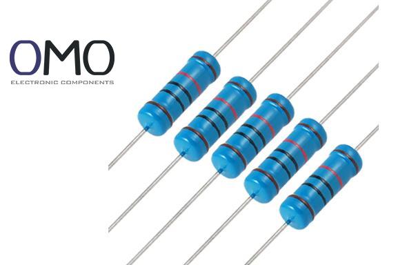
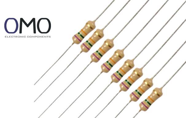
By material: Carbon film, metal film, metal oxide film, wire-wound, thick film chip, thin film chip resistors.
By function:
Fixed resistor: Constant resistance. Most common.
Variable resistor: Such as potentiometer (volume knob) and trimmer (fine tuning).
Sensitive resistor:
Thermistor (temperature sensing)
Photoresistor (light control)
Varistor (over-voltage protection)
Power resistor: Designed for high current and better heat handling.
By packaging:
Axial leads (common in old radios)
Radial leads
Surface mount (SMD, widely used now)
Power resistors with heatsinks
Parameters and Features: The Performance Scale
“Nominal” vs “Actual” Resistance
Nominal resistance: The labeled value on the resistor, following international E-series (e.g., E24 provides 24 values per decade).
Tolerance: The allowed error range between actual and nominal value. Common tolerances:
±1% (precision)
±5% (general use)
±10%, ±20% (low-cost or high-tolerance cases)
Nominal Resistance (Ω)
±1% Range (Ω)
±5% Range (Ω)
Example Applications
100
99-101
95-105
General voltage dividing, current limiting
1k(1000)
990-1010
950-1050
LED driver, biasing
10k
9900-10100
9500-10500
Pull-up/pull-down, sensors
100k
99000-101000
95000-105000
Feedback network, high resistance circuits
Power Rating: The Maximum Limit
Rated power is the highest power (in watts, W) the resistor can handle safely over time.
Important: Never exceed the rated power!
If power is too high, the resistor overheats and burns. Too low, and you waste space and cost.
Common ratings: 1/16W, 1/8W, 1/4W, 1/2W, 1W, 5W.
Temperature and Voltage Limits
TCR (Temperature Coefficient of Resistance): Shows how much the resistance changes with temperature. Unit: ppm/°C (parts per million per °C).
Carbon film: ±350–1000 ppm/°C
Metal film: ±50–100 ppm/°C
Premium metal foil: as low as ±2 ppm/°C, less than 0.02% change from –55°C to +155°C.
Maximum working voltage: The highest safe continuous voltage (DC or RMS).
High-resistance resistors need extra care to avoid breakdown from internal discharge.
Survival Limits and Power Derating
Maximum voltage: The peak voltage the resistor can handle briefly without damage. Higher than working voltage.
Power derating: At high temperatures or in sealed spaces, the resistor can’t cool well. Follow derating curves to reduce power use and extend lifespan.
Example: A 1W resistor may need to work as 0.8W at 70°C, and just 0.5W at 100°C.
Role in Circuits: A Multi-Tool Performer
Resistors are the Swiss Army knife of electronics:
Current limiting: In series with LEDs to prevent overcurrent; protect IC pins.
Voltage dividing: Create reference voltages in divider networks (e.g., for power monitoring).
Signal biasing/level setting: Set Q-point for transistors or op-amps.
Impedance matching: Reduce signal reflection in RF circuits.
Energy dissipation: Brake resistors absorb energy from motors; heating uses Joule effect.
Feedback networks: With capacitors/inductors in op-amps or power loops, control system response.
Pull-up/Pull-down resistors: Set stable logic high/low at digital I/O pins to avoid noise.
How to Control Current: Practical Use of Ohm’s Law
Key formula: I = V / R (Ohm’s Law)
You can control current in several ways:
Series resistors: Increase resistance to limit current. Simple and direct.
Parallel resistors:
Divert current through a low-resistance path (e.g., sense big current using milliohm resistor)
Provide small leakage path (e.g., pull-down for MOSFET gate)
Change resistance: Use potentiometers, digital pots, or photo/thermal resistors for dynamic control.
Adjust voltage source: Keep resistance fixed and fine-tune supply voltage to control current (e.g., constant current source).
Application Scenarios: From Basic to Advanced
Resistors play core roles in many areas:
Circuit protection: Current limiting for LEDs or IC inputs/outputs.
Signal conditioning: Gain setting resistors (Rf, Rin) for op-amps; RC or RL filters.
Power sharing and conversion: Load balancing, dummy loads for startup, current sensing with milliohm resistors.
Precision measurement: Wheatstone bridge, voltage dividers, sensor resistors (NTC/PTC/LDR).
Logic control: Pull-up/pull-down resistors to ensure stable logic at I/O ports.
EMC design: Damping resistors on PCB signal lines to reduce ringing (overshoot/undershoot).
Selection and Use: Practice Brings Understanding
Choosing the right resistor is both a technical and cost decision. Key factors:
Target resistance (based on circuit needs)
Expected and peak voltages (don’t exceed limits)
Power and temperature conditions (calculate dissipation and derating)
Precision (±1% or better for accurate jobs)
TCR (temperature stability) (low TCR for wide temp ranges)
Working frequency (low parasitics for high frequency—use thin film or SMD)
Size, cost, availability (SMD resistors are cheap and fit auto-assembly)
Reading the “Code” of Resistors
Color band resistors: 4 or more color rings show resistance and tolerance.
Example: Brown (1), Black (0), Red (×100), Gold (±5%) = 10 × 100 = 1kΩ ±5%
SMD resistor codes:
3 or 4 digits, with the last digit as a power of 10.
Example: 103 = 10 × 10³ = 10kΩ
Precision code: 01C = 102 (E96 series, 10kΩ)
Golden Rules for Reliable Operation
Respect power limits: Always derate in high temp or enclosed areas.
Ensure good heat dissipation: Power resistors need heatsinks and airflow.
Watch the voltage: Never go over rated or maximum voltage, especially for high-ohm types.
Fit the environment: Choose moisture-proof, anti-corrosion, and vibration-proof types (SMD or reinforced wire-wound).
Layout wisely:
Keep power resistors away from heat-sensitive parts.
Shorten leads in high-frequency use to reduce parasitic effects.
Frequently Asked Questions
Does a resistor reduce voltage?
Yes, resistors can cause a voltage drop in a circuit. This happens because they dissipate electrical energy as heat, consistent with Ohm's Law.
How much does a resistor reduce voltage?
Two main factors determine the voltage drop across a resistor: its resistance (R) and the current (I) passing through it.
How to reduce current without affecting voltage?
Current reduction without altering circuit voltage can be achieved by inserting a series resistor or adjusting the load impedance (for AC systems).
Does current change across a resistor in parallel?
In a parallel circuit, the voltage is identical across all branches. However, the current differs through each resistor, proportional to the individual resistance.